Fire Rakshak-DTS(Distributed Temperature sensing)
Technica Fire Rakshak
Fire Rakshak is a Linear Heat Detector System specifically designed for Industrial Applications
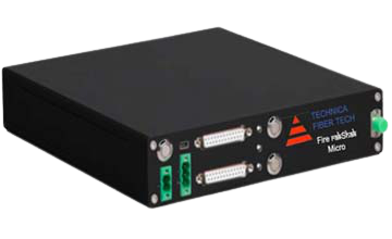
The Fire Rakshak Distributed Temperature Sensing (DTS) system connects to a distributed fiber optic cable (FireFiber) and determines temperature and distance data at thousands of points along the length of the cable. The fiber optic cable is installed within the asset to be protected and this cable acts as the sensing element.
The Fire Rakshak Sensor Control Unit is responsible for generating alarms based upon the calculated temperature profile. The Fire Rakshak DTS can therefore detect the location of a hot spot on up to a 5km length of fiber optic cable with unrivaled precision. The system is able to monitor the movement of the hot spot, or multiple hot spots, in terms of physical position, temperature and also in real-time. Fire Rakshak Distributed Temperature Sensing Technology provides a line type heat detector solution vastly superior to conventional copper based or multipoint heat detector.
Front Panel & Key Features
- 1U half rack width - compact design
- RS485 MODBUS interface in master slave topology
- Full temperature trace available via MODBUS registers
- Relay outputs for alarm interface
- USB interface for convenient connectivity
- Low power consumption (8.5W)
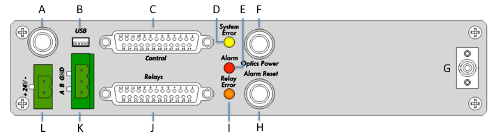
Front Panel Components
Item |
Description |
Type |
Function |
|---|---|---|---|
| A | Main Power switch | Push button with GREEN indicator | Push to turn on. Press and hold >5s to turn off Steady Green: Powered ON |
| B | USB Interface | Mini-B | Direct PC interface |
| C | Control Interface | DB-25 female | Control inputs and system light outputs |
| D | Indicator: System error | YELLOW LED | Indicates system error Steady Yellow: Fiber break error Flashing Yellow: Data save error |
| E | Indicator: Alarm | RED LED | Indicates temperature alarm Steady Red: Temperature alarm |
| F | Optics power switch | Optics power switch | Switches laser on or off. Push and hold >3s to toggle between on / off states Steady Blue: Optics power is ON Flashing Blue: Data acquisition in progress. Optics powered + Laser is active OFF: Optics power is OFF |
| G | Sensor cable connector | FC/APC connector | Connection point for 62.5um graded index multimode sensing fibre |
| H | Alarm reset | Push button with RED indicator | Resets the triggered alarm. Press and hold >2s to reset alarms |
| I | Indicator: Relay error | ORANGE LED | Indicates that a relay output has failed to close |
| J | Relay output connector | DB-25 female | Relay outputs. Max 48VDC 1A. |
| K | RS-485 | 3-pin 5.08mm terminal block | RS-485 communication
TOP: GND MID: B (-ve) BOT: A (+ve) |
| L | Power input | 2-pin 5.08mm terminal block | Main power in: 24VDC TOP: -ve BOT: +ve |
System Specifications
| Measurement Range | 500 metres | 1,500 metres |
| Temperature Resolution | 0.5°C @ 5 seconds | 1.6°C @ 5 seconds |
| Spatial Resolution | Best 1.6 m | 3m |
| Sampling resolution | 1m | 2m |
| Measurement time | 5s < t < 20min | 5s < t < 20min |
| Channels | 1 | |
| Optical fiber type | Multimode 62.5um/125um (50um option available resolution lower spec), FC/APC connector |
|
| Zone Information | 10 Configurable smart zones | |
| Power Requirements | 24VDC, 8.5W | |
| Alarm Types | Maximum temperature Minimum temperature Rate of change | |
| Switches | Power on/off, Optics power control on/off, alarm reset | |
| Indicators | Temperature alarm, relay error, optics power, system error | |
| Communication interface & Protocol | RS485 & USB. MODBUS supported
functions 0x02, 0x03, 0x04, 0x05, 0x06, 0x10 Relay outputs – 3 system, 5 user power, general alarm, system error, (laser and sensor fault), (DB25) |
|
| Data Storage | 4GB | |
| Operating Environment | Operating temperature:-10°C to +50°C Storage temperature:-40°C to +85°C Temp sensing range: cable dependent | |
| Physical Dimensions | H*D*W: 44mm*246mm*220mm | |
| Weight | 2.0 kg |

Applications Summary
- Main hangar and Maintenance Hangers
- Inside tunnels and subways.
- Electrical bus wiring and electrical Panel.
- Escalator and travelator
- Airport waiting lounge
- ATC Tower and other facilities Buildings
- Airport Power generation and Battery Room
- Catering and food court
- Cargo building